Featured Post
 Featured Post
8.4.1.2 Packet Tracer - Skills Integration Challenge
8.4.1.2 Packet Tracer - Skills Integration Challenge Addressing Table Scenario Your company has won a contract to set up a smal...
Panduan Konfigurasi Dasar pada Perangkat Mikrotik

Tools yang digunakan:
- PC/Laptop
- Mikrotik hAP Lite dengan Router OS 6.43.16
- Winbox (64bit)
 |
| Topologi yang digunakan |
1. Login ke Mikrotik menggunakan aplikasi Winbox
Jika perangkat mikrotik kamu masih baru, kamu bisa login menggunakan IP Address default yaitu 192.168.88.1 dengan user admin dan password dikosongin. Setelah berhasil login, bisa kamu remove configuration, kemudian kamu akan diminta login kembali, dan bisa menggunakan MAC Address.

2. Konfigurasi Nama Perangkat
- Pilih menu System - Identity
- Masukkan nama yang diinginkan
- Pilih Apply lalu OK

3. Konfigurasi Password Login perangkat Mikrotik
- Pilih menu Systems - Password
- Masukkan password yang baru

4. Konfigurasi IP Address
- Pilih menu IP - Addresses
- Konfigurasi IP Address ke ISP
- Klik icon +
- Masukkan Address 192.168.8.2/24
- Network : 192.168.8.0
- Interface : ether1
- Klik Comment untuk memberi catatan, contoh : ISP
- Konfigurasi IP Address ke Jaringan LAN
- Klik icon +
- Masukkan Address 192.168.1.1/24
- Network : 192.168.1.0
- Interface : ether2
- Klik Comment untuk memberi catatan, contoh : LAN
5. Konfigurasi NAT
- Pilih menu IP - Firewall - tab NAT
- Klik icon +
- di tab General, chain : srcnat ; Out. Interface : ether1
- di tab Action, pilih masquerade
- Klik Apply lalu OK
6. Konfigurasi DNS
- Pilih menu IP - DNS
- Servers diisi dengan 8.8.8.8
- Tick pada bagian Allow Remote Requests
7. Konfigurasi Routing
- Pilih menu IP - Route
- Klik icon +
- Dst Address diisi 0.0.0.0
- Gateway diisi dengan IP 192.168.8.1
- Klik Apply lalu OK
8. Konfigurasi IP Address pada Komputer Klien
9. Selesai
Soni Setiawan 20:44:00 New Google SEO Bandung, Indonesia

10.2.2.8 Packet Tracer - DNS and DHCP
Packet Tracer - DHCP and DNS Servers
Objectives
Part 1: Configure Static IPv4 Addressing
Part 2: Configure and Verify DNS Records
Background
In this activity, you will configure and verify static IP addressing and DHCP addressing. You will then configure a DNS server to map IP addresses to the website names.
Note: Packet Tracer only simulates the process for configuring these services. DHCP and DNS software packages each have their own unique installation and configuration instructions.
Part 1: Configure Static IPv4 Addressing
Step 1: Configure the Inkjet printer with static IPv4 addressing.
The home office computers need to know the printer’s IPv4 address to send information to it. The printer, therefore, must use a static (unchanging) IPv4 address.
a. Click Inkjet and click the Config tab, which displays the Global Settings.
b. Statically assign the Gateway address as 192.168.0.1 and the DNS Server address as 64.100.8.8.
c. Click FastEthernet0 and statically assign the IP address as 192.168.0.2 and the Subnet Mask address as 255.255.255.0.
d. Close the Inkjet window.

Step 2: Configure WRS to provide DHCP services.
a. Click WRS and click the GUI tab, and maximize the window.
b. The Basic Setup window displays, by default. Configure the following settings in the Network Setup section:
1) Change the IP Address to 192.168.0.1.
2) Set the Subnet Mask to 255.255.255.0.
3) Enable the DHCP Server.
4) Set the Static DNS 1 address to 64.100.8.8.
5) Scroll to the bottom and click Save.
c. Close the WRS window.

Step 3: Request DHCP addressing for the home laptop.
This activity focuses on the home office. The clients that you will configure with DHCP are Home Laptop and Tablet.
a. Click Home Laptop and click the Desktop tab > IP Configuration.
b. Click DHCP and wait until the DHCP request is successful.
c. Home Laptop should now have a full IP configuration. If not, return to Step 2 and verify your configurations on WRS.
d. Close the IP Configuration window and then close the Home Laptop window.

Step 4: Request DHCP addressing for the tablet.
a. Click Tablet and click the Desktop tab > IP Configuration.
b. Click DHCP and wait until the DHCP request is successful.
c. Tablet should now have a full IP configuration. If not, return to Step 2 and verify your configurations on WRS.

Step 5: Test access to websites.
a. Close the IP Configuration window, and then click Web Browser.
b. In the URL box, type 10.10.10.2 (for the CentralServer website) or 64.100.200.1 (for the BranchServer website) and click Go. Both websites should appear.
c. Reopen the web browser. Test the names for those same websites by entering centralserver.pt.pka and branchserver.pt.pka. Click on Fast Forward Time on the yellow bar below the topology to speed the process.

Part 2: Configure Records on the DNS Server
Step 1: Configure famous.dns.pka with records for CentralServer and BranchServer.
Typically, DNS records are registered with companies, but for the purposes of this activity you control the famous.dns.pka server on the Internet.
a. Click the Internet cloud. A new network displays.
b. Click famous.dns.pka and click the Config tab > DNS.
c. Add the following resource records:
d. Close the famous.dns.pka window.
e. Click Back to exit the Internet cloud.

Step 2: Verify the ability of client computers to use DNS.
Now that you have configured DNS records, Home Laptop and Tablet should be able to access the websites by using the names instead of the IP addresses. First, check that the DNS client is working properly and then verify access to the website.
a. Click Home Laptop or Tablet.
b. If the web browser is open, close it and select Command Prompt.
c. Verify the IPv4 addressing by entering the command ipconfig /all. You should see the IP address for the DNS server.
d. Ping the DNS server at 64.100.8.8 to verify connectivity.
Note: The first two or three pings may fail as Packet Tracer simulates all the various processes that must occur for successful connectivity to a remote resource.
e. Test the functionality of the DNS server by entering the commands nslookup centralserver.pt.pka and nslookup branchserver.pt.pka. You should get a name resolution showing the IP address for each.
f. Close the Command Prompt window and click Web Browser. Verify that Home Laptop or Tablet can now access the web pages for CentralServer and BranchServer.
Soni Setiawan
20:06:00
New Google SEO
Bandung, IndonesiaPacket Tracer - DHCP and DNS Servers
Objectives
Part 1: Configure Static IPv4 Addressing
Part 2: Configure and Verify DNS Records
Background
In this activity, you will configure and verify static IP addressing and DHCP addressing. You will then configure a DNS server to map IP addresses to the website names.
Note: Packet Tracer only simulates the process for configuring these services. DHCP and DNS software packages each have their own unique installation and configuration instructions.
Part 1: Configure Static IPv4 Addressing
Step 1: Configure the Inkjet printer with static IPv4 addressing.
The home office computers need to know the printer’s IPv4 address to send information to it. The printer, therefore, must use a static (unchanging) IPv4 address.
a. Click Inkjet and click the Config tab, which displays the Global Settings.
b. Statically assign the Gateway address as 192.168.0.1 and the DNS Server address as 64.100.8.8.
c. Click FastEthernet0 and statically assign the IP address as 192.168.0.2 and the Subnet Mask address as 255.255.255.0.
d. Close the Inkjet window.

Step 2: Configure WRS to provide DHCP services.
a. Click WRS and click the GUI tab, and maximize the window.
b. The Basic Setup window displays, by default. Configure the following settings in the Network Setup section:
1) Change the IP Address to 192.168.0.1.
2) Set the Subnet Mask to 255.255.255.0.
3) Enable the DHCP Server.
4) Set the Static DNS 1 address to 64.100.8.8.
5) Scroll to the bottom and click Save.
c. Close the WRS window.

Step 3: Request DHCP addressing for the home laptop.
This activity focuses on the home office. The clients that you will configure with DHCP are Home Laptop and Tablet.
a. Click Home Laptop and click the Desktop tab > IP Configuration.
b. Click DHCP and wait until the DHCP request is successful.
c. Home Laptop should now have a full IP configuration. If not, return to Step 2 and verify your configurations on WRS.
d. Close the IP Configuration window and then close the Home Laptop window.

Step 4: Request DHCP addressing for the tablet.
a. Click Tablet and click the Desktop tab > IP Configuration.
b. Click DHCP and wait until the DHCP request is successful.
c. Tablet should now have a full IP configuration. If not, return to Step 2 and verify your configurations on WRS.

Step 5: Test access to websites.
a. Close the IP Configuration window, and then click Web Browser.
b. In the URL box, type 10.10.10.2 (for the CentralServer website) or 64.100.200.1 (for the BranchServer website) and click Go. Both websites should appear.
c. Reopen the web browser. Test the names for those same websites by entering centralserver.pt.pka and branchserver.pt.pka. Click on Fast Forward Time on the yellow bar below the topology to speed the process.

Part 2: Configure Records on the DNS Server
Step 1: Configure famous.dns.pka with records for CentralServer and BranchServer.
Typically, DNS records are registered with companies, but for the purposes of this activity you control the famous.dns.pka server on the Internet.
a. Click the Internet cloud. A new network displays.
b. Click famous.dns.pka and click the Config tab > DNS.
c. Add the following resource records:
d. Close the famous.dns.pka window.
e. Click Back to exit the Internet cloud.

Step 2: Verify the ability of client computers to use DNS.
Now that you have configured DNS records, Home Laptop and Tablet should be able to access the websites by using the names instead of the IP addresses. First, check that the DNS client is working properly and then verify access to the website.
a. Click Home Laptop or Tablet.
b. If the web browser is open, close it and select Command Prompt.
c. Verify the IPv4 addressing by entering the command ipconfig /all. You should see the IP address for the DNS server.
d. Ping the DNS server at 64.100.8.8 to verify connectivity.
Note: The first two or three pings may fail as Packet Tracer simulates all the various processes that must occur for successful connectivity to a remote resource.
e. Test the functionality of the DNS server by entering the commands nslookup centralserver.pt.pka and nslookup branchserver.pt.pka. You should get a name resolution showing the IP address for each.
f. Close the Command Prompt window and click Web Browser. Verify that Home Laptop or Tablet can now access the web pages for CentralServer and BranchServer.

10.2.1.8 Packet Tracer - Web and Mail
Objectives
Part 1: Configure and Verify Web Services
Part 2: Configure and Verify Email Services
Background
In this activity, you will configure HTTP and email services using the simulated server in Packet Tracer. You will then configure clients to access the HTTP and email services.
Note: Packet Tracer only simulates the process for configuring these services.
HTTP and email software packages each have their own unique installation and configuration instructions.
Part 1: Configure and Verify Web Services
Step 1: Configure web services on CentralServer and BranchServer.
a. Click CentralServer and click the Config tab > HTTP.
b. Click On to enable HTTP and HTTP Secure (HTTPS).
c. Optional. Personalize the HTML code.
d. Repeat Step1a – 1c on BranchServer.
Step 2: Verify the web servers by accessing the web pages.
There are many endpoint devices in this network, but for the purposes of this step, use PC3.
a. Click PC3 and click the Desktop tab > Web Browser.
b. In the URL box, enter 10.10.10.2 as the IP address and click Go. The CentralServer website displays.
c. In the URL box, enter 64.100.200.1 as the IP address and click Go. The BranchServer website displays.
d. In the URL box, enter centralserver.pt.pka and click Go. The CentralServer website displays.
e. In the URL box, enter branchserver.pt.pka and click Go. The BranchServer website displays.
f. What protocol is translating the centralserver.pt.pka and branchserver.pt.pka names to IP addresses?
Part 2: Configure and Verify Email Services on Servers
Step 1: Configure CentralServer to send (SMTP) and receive (POP3) Email.
a. Click CentralServer, and then select the Config tab followed by the EMAIL button.
b. Click On to enable the SMTP and POP3.
c. Set the domain name to centralserver.pt.pka and click Set.
d. Create a user named central-user with password cisco. Click + to add the user.

Step 2: Configure BranchServer to send (SMTP) and receive (POP3) Email.
a. Click BranchServer and click the Config tab > EMAIL.
b. Click On to enable SMTP and POP3 .
c. Set the domain name to branchserver.pt.pka and click Set.
d. Create a user named branch-user with password cisco. Click + to add the user.

Step 3: Configure PC3 to use the CentralServer email service.
a. Click PC3 and click the Desktop tab > E Mail.
b. Enter the following values into their respective fields:
1) Your Name: Central User
2) Email Address: central-user@centralserver.pt.pka
3) Incoming Mail Server: 10.10.10.2
4) Outgoing Mail Server: 10.10.10.2
5) User Name: central-user
6) Password: cisco
c. Click Save. The Mail Browser window displays.
d. Click Receive. If everything has been set up correctly on both the client and server, the Mail Browser window displays the Receive Mail Success message confirmation.

Step 4: Configure Sales to use the Email service of BranchServer.
a. Click Sales and click the Desktop tab > E Mail.
b. Enter the following values into their respective fields:
1) Your Name: Branch User
2) Email Address: branch-user@branchserver.pt.pka
3) Incoming Mail Server: 172.16.0.3
4) Outgoing Mail Server: 172.16.0.3
5) User Name: branch-user
6) Password: cisco
c. Click Save. The Mail Browser window displays.
d. Click Receive. If everything has been set up correctly on both the client and server, the Mail Browser window displays the Receive Mail Success message confirmation.
e. The activity should be 100% complete. Do not close the Sales configuration window or the Mail Browser window.

Step 5: Send an Email from the Sales client and the PC3 client.
a. From the Sales Mail Browser window, click Compose.
b. Enter the following values into their respective fields:
1) To: central-user@centralserver.pt.pka
2) Subject: Personalize the subject line.
3) Email Body: Personalize the email.
c. Click Send.
d. Verify that PC3 received the email. Click PC3. If the Mail Browser window is closed, click E Mail.
e. Click Receive. An email from Sales displays. Double-click the email.
f. Click Reply, personalize a response, and click Send.
g. Verify that Sales received the reply.

Soni Setiawan
00:51:00
New Google SEO
Bandung, IndonesiaObjectives
Part 1: Configure and Verify Web Services
Part 2: Configure and Verify Email Services
Background
In this activity, you will configure HTTP and email services using the simulated server in Packet Tracer. You will then configure clients to access the HTTP and email services.
Note: Packet Tracer only simulates the process for configuring these services.
HTTP and email software packages each have their own unique installation and configuration instructions.
Part 1: Configure and Verify Web Services
Step 1: Configure web services on CentralServer and BranchServer.
a. Click CentralServer and click the Config tab > HTTP.
b. Click On to enable HTTP and HTTP Secure (HTTPS).
c. Optional. Personalize the HTML code.
d. Repeat Step1a – 1c on BranchServer.
Step 2: Verify the web servers by accessing the web pages.
There are many endpoint devices in this network, but for the purposes of this step, use PC3.
a. Click PC3 and click the Desktop tab > Web Browser.
b. In the URL box, enter 10.10.10.2 as the IP address and click Go. The CentralServer website displays.
c. In the URL box, enter 64.100.200.1 as the IP address and click Go. The BranchServer website displays.
d. In the URL box, enter centralserver.pt.pka and click Go. The CentralServer website displays.
e. In the URL box, enter branchserver.pt.pka and click Go. The BranchServer website displays.
f. What protocol is translating the centralserver.pt.pka and branchserver.pt.pka names to IP addresses?
Part 2: Configure and Verify Email Services on Servers
Step 1: Configure CentralServer to send (SMTP) and receive (POP3) Email.
a. Click CentralServer, and then select the Config tab followed by the EMAIL button.
b. Click On to enable the SMTP and POP3.
c. Set the domain name to centralserver.pt.pka and click Set.
d. Create a user named central-user with password cisco. Click + to add the user.

Step 2: Configure BranchServer to send (SMTP) and receive (POP3) Email.
a. Click BranchServer and click the Config tab > EMAIL.
b. Click On to enable SMTP and POP3 .
c. Set the domain name to branchserver.pt.pka and click Set.
d. Create a user named branch-user with password cisco. Click + to add the user.

Step 3: Configure PC3 to use the CentralServer email service.
a. Click PC3 and click the Desktop tab > E Mail.
b. Enter the following values into their respective fields:
1) Your Name: Central User
2) Email Address: central-user@centralserver.pt.pka
3) Incoming Mail Server: 10.10.10.2
4) Outgoing Mail Server: 10.10.10.2
5) User Name: central-user
6) Password: cisco
c. Click Save. The Mail Browser window displays.
d. Click Receive. If everything has been set up correctly on both the client and server, the Mail Browser window displays the Receive Mail Success message confirmation.

Step 4: Configure Sales to use the Email service of BranchServer.
a. Click Sales and click the Desktop tab > E Mail.
b. Enter the following values into their respective fields:
1) Your Name: Branch User
2) Email Address: branch-user@branchserver.pt.pka
3) Incoming Mail Server: 172.16.0.3
4) Outgoing Mail Server: 172.16.0.3
5) User Name: branch-user
6) Password: cisco
c. Click Save. The Mail Browser window displays.
d. Click Receive. If everything has been set up correctly on both the client and server, the Mail Browser window displays the Receive Mail Success message confirmation.
e. The activity should be 100% complete. Do not close the Sales configuration window or the Mail Browser window.

Step 5: Send an Email from the Sales client and the PC3 client.
a. From the Sales Mail Browser window, click Compose.
b. Enter the following values into their respective fields:
1) To: central-user@centralserver.pt.pka
2) Subject: Personalize the subject line.
3) Email Body: Personalize the email.
c. Click Send.
d. Verify that PC3 received the email. Click PC3. If the Mail Browser window is closed, click E Mail.
e. Click Receive. An email from Sales displays. Double-click the email.
f. Click Reply, personalize a response, and click Send.
g. Verify that Sales received the reply.


9.1.4.6 Packet Tracer - Subnetting Scenario 1
Soni Setiawan
22:15:00
New Google SEO
Bandung, Indonesia |
| Topologi |
Objectives
Part 1: Design an IP Addressing Scheme
Part 2: Assign IP Addresses to Network Devices and Verify Connectivity
Scenario
In this activity, you are given the network address of 192.168.100.0/24 to subnet and provide the IP addressing for the network shown in the topology. Each LAN in the network requires enough space for, at least, 25 addresses for end devices, the switch and the router. The connection between R1 to R2 will require an IP address for each end of the link.
Part 1: Design an IP Addressing Scheme
Step 1: Subnet the 192.168.100.0/24 network into the appropriate number of subnets.
a. Based on the topology, how many subnets are needed?
b. How many bits must be borrowed to support the number of subnets in the topology table?
c. How many subnets does this create?
d. How many usable hosts does this create per subnet?
Note: If your answer is less than the 25 hosts required, then you borrowed too many bits.
e. Calculate the binary value for the first five subnets. The first subnet is already shown.
Selanjutnya, PAHAMI bagian ini
Step 2: Assign the subnets to the network shown in the topology.
a. Assign Subnet 0 to the LAN connected to the GigabitEthernet 0/0 interface of R1:
b. Assign Subnet 1 to the LAN connected to the GigabitEthernet 0/1 interface of R1:
c. Assign Subnet 2 to the LAN connected to the GigabitEthernet 0/0 interface of R2:
d. Assign Subnet 3 to the LAN connected to the GigabitEthernet 0/1 interface of R2:
e. Assign Subnet 4 to the WAN link between R1 to R2:
Step 3: Document the addressing scheme.
Fill in the Addressing Table using the following guidelines:
a. Assign the first usable IP addresses to R1 for the two LAN links and the WAN link.
b. Assign the first usable IP addresses to R2 for the LANs links. Assign the last usable IP address for the WAN link.
c. Assign the second usable IP addresses to the switches.
d. Assign the last usable IP addresses to the hosts.
Part 2: Assign IP Addresses to Network Devices and Verify Connectivity
Most of the IP addressing is already configured on this network. Implement the following steps to complete the addressing configuration.
Step 1: Configure IP addressing on R1 LAN interfaces.
R1>enable
R1#configure terminal
Enter configuration commands, one per line. End with CNTL/Z.
R1(config)#interface gigabitEthernet 0/0
R1(config-if)#ip address 192.168.100.1 255.255.255.224
R1(config-if)#no shutdown
R1(config-if)#
R1(config-if)#int g0/1
R1(config-if)#ip address 192.168.100.33 255.255.255.224
R1(config-if)#no shutdown
R1(config-if)#
Step 2: Configure IP addressing on S3, including the default gateway.
S3>enable
S3#configure terminal
Enter configuration commands, one per line. End with CNTL/Z.
S3(config)#interface vlan 1
S3(config-if)#ip add 192.168.100.66 255.255.255.224
S3(config-if)#no shutdown
S3(config-if)#exit
S3(config)#ip default-gateway 192.168.100.65
S3(config)#
Step 3: Configure IP addressing on PC4, including the default gateway.
Step 4: Verify connectivity.
Part 1: Design an IP Addressing Scheme
Part 2: Assign IP Addresses to Network Devices and Verify Connectivity
Scenario
In this activity, you are given the network address of 192.168.100.0/24 to subnet and provide the IP addressing for the network shown in the topology. Each LAN in the network requires enough space for, at least, 25 addresses for end devices, the switch and the router. The connection between R1 to R2 will require an IP address for each end of the link.
Part 1: Design an IP Addressing Scheme
Step 1: Subnet the 192.168.100.0/24 network into the appropriate number of subnets.
a. Based on the topology, how many subnets are needed?
b. How many bits must be borrowed to support the number of subnets in the topology table?
c. How many subnets does this create?
d. How many usable hosts does this create per subnet?
Note: If your answer is less than the 25 hosts required, then you borrowed too many bits.
e. Calculate the binary value for the first five subnets. The first subnet is already shown.
Sebenarnya agak bingung juga mau jelasin dari mana, namun yang saya pahami ketika mengerjakan latihan ini adalah bagaimana alokasi IP Address dimana disediakan 1 (satu) IP Address yang kemudian dibagi-bagi/di subnet sehingga mencakup seluruh kebutuhan IP Address berdasarkan topologi yang telah ditentukan.
Subnetting
Hal pertama yang terpikirkan olehku adalah subnet. Ya, karena pembagian/alokasi IP Address jika disediakan 1 (satu) IP Address maka berkaitan dengan subnet/subnetting. Maka yang dilakukan adalah mengotak-atik subnet mask dari IP Address yang telah disediakan tadi.
- Dibutuhkan IP Address untuk 25 hosts
- Tentukan subnet yang memenuhi persyaratan di atas
<!-- Cara yang aku lakukan -->
11111111.11111111.11111111.11100000
Untuk mengetahui jumlah host per subnet gunakan rumus :
2^n-2
dimana : n adalah jumlah angka 0 di oktet terakhir
maka
2^5-2 = 30 (memenuhi syarat butuh 25 hosts)
Berdasarkan kebutuhan tersebut, subnet yang memenuhi adalah /27
Terus ???
Yang saya lakukan adalah menentukan range IP Address yang digunakan dalam 1 subnet.
Biar lebih mudah, aku pake LibreOffice Calc (kayak Excel) untuk menentukan range IP Address.
 |
| Alokasi IP Address |
Step 2: Assign the subnets to the network shown in the topology.
a. Assign Subnet 0 to the LAN connected to the GigabitEthernet 0/0 interface of R1:
b. Assign Subnet 1 to the LAN connected to the GigabitEthernet 0/1 interface of R1:
c. Assign Subnet 2 to the LAN connected to the GigabitEthernet 0/0 interface of R2:
d. Assign Subnet 3 to the LAN connected to the GigabitEthernet 0/1 interface of R2:
e. Assign Subnet 4 to the WAN link between R1 to R2:
Step 3: Document the addressing scheme.
Fill in the Addressing Table using the following guidelines:
a. Assign the first usable IP addresses to R1 for the two LAN links and the WAN link.
b. Assign the first usable IP addresses to R2 for the LANs links. Assign the last usable IP address for the WAN link.
c. Assign the second usable IP addresses to the switches.
d. Assign the last usable IP addresses to the hosts.
Part 2: Assign IP Addresses to Network Devices and Verify Connectivity
Most of the IP addressing is already configured on this network. Implement the following steps to complete the addressing configuration.
Step 1: Configure IP addressing on R1 LAN interfaces.
R1>enable
R1#configure terminal
Enter configuration commands, one per line. End with CNTL/Z.
R1(config)#interface gigabitEthernet 0/0
R1(config-if)#ip address 192.168.100.1 255.255.255.224
R1(config-if)#no shutdown
R1(config-if)#
R1(config-if)#int g0/1
R1(config-if)#ip address 192.168.100.33 255.255.255.224
R1(config-if)#no shutdown
R1(config-if)#
Step 2: Configure IP addressing on S3, including the default gateway.
S3>enable
S3#configure terminal
Enter configuration commands, one per line. End with CNTL/Z.
S3(config)#interface vlan 1
S3(config-if)#ip add 192.168.100.66 255.255.255.224
S3(config-if)#no shutdown
S3(config-if)#exit
S3(config)#ip default-gateway 192.168.100.65
S3(config)#
Step 3: Configure IP addressing on PC4, including the default gateway.
 |
| PC4 IP Address |
Step 4: Verify connectivity.
 |
| Tes Koneksi PC4 ke PC1 |

Running Packet Tracer 6.3 on Ubuntu 14.04 - Setelah beberapa hari terakhir mengalami kesulitan untuk menjalankan packet tracer ver 6.3 di Ubuntu yang saya gunakan, akhirnya setelah saya reinstall dengan langkah instalasi yang berbeda sukses di lakukan.
Beberapa bulan terakhir sedang menyusun tugas akhir alias skripsi menjadikan jarang menggunakan packet tracer untuk belajar materi jaringan. Terlebih lagi saya mengganti laptop, iya bener saya ganti laptop karena laptop yang sudah diinstal packet tracer sebelumnya sudah rusak. Jadi mau tidak mau harus ganti laptop.
Ini tampilan packet tracer yang berhasil dijalankan pada Ubuntu 14.04 yang saya pake.
 |
| Packet Tracer v6.3 on Ubuntu 14.04 |
Sudah terinstal, saatnya kembali belajar. Jangan pernah berhenti belajar, guys! Belajar tentang segala hal. Hehee ;)

6.5.1.2 Packet Tracer Skills Integration Challenge
Objectives
Finish the network documentation.
Perform basic device configurations on a router and a switch.
Verify connectivity and troubleshoot any issues.
Scenario
Your network manager is impressed with your performance in your job as a LAN technician. She would like you to now demonstrate your ability to configure a router connecting two LANs. Your tasks include configuring basic settings on a router and a switch using the Cisco IOS. You will then verify your configurations, as well as configurations on existing devices by testing end-to-end connectivity.
Note: After completing this activity, you can choose to click the Reset Activity button to generate a new set of requirements. Variable aspects include device names, IP addressing schemes, and the topology.
Requirements
· Provide the missing information in the Addressing Table.
#You will find a miss configuration on Reception-B
#Change to correct ip address configuration : 10.10.11.102
Name the router Floor14 and the second switch Room-146. You will not be able to access Room-145.
#router Floor14
Router>enable
Router#configure terminal
Enter configuration commands, one per line. End with CNTL/Z.
Router(config)#hostname Floor14
Floor14(config)#exit
Floor14#
#switch Room-146
Switch#enable
Switch#configure terminal
Enter configuration commands, one per line. End with CNTL/Z.
Switch(config)#hostname Room-146
Room-146(config)#exit
Room-146#
Use cisco as the user EXEC password for all lines.
Use class as the privileged EXEC password.
Encrypt all plain text passwords.
Configure an appropriate banner.
Configure addressing for all devices according to the Addressing Table.
Document interfaces with descriptions, including the Room-146 VLAN 1 interface.
Save your configurations.
Verify connectivity between all devices. All devices should be able to ping any other device.
#router Floor14
Floor14>enable
Floor14#configure terminal
Enter configuration commands, one per line. End with CNTL/Z.
Floor14(config)#line console 0
Floor14(config-line)#password cisco
Floor14(config-line)#login
Floor14(config-line)#exit
Floor14(config)#line vty 0
Floor14(config-line)#password cisco
Floor14(config-line)#login
Floor14(config-line)#exit
Floor14(config)#enable secret class
Floor14(config)#service pass
Floor14(config)#service password-encryption
Floor14(config)#banner motd &
Enter TEXT message. End with the character '&'.
Authorized Access Only! &
Floor14(config)#
Floor14(config)#interface gigabitEthernet 0/0
Floor14(config-if)#ip add 10.10.10.1 255.255.255.0
Floor14(config-if)#no shutdown
Floor14(config-if)#exit
Floor14(config)#interface gigabitEthernet 0/1
Floor14(config-if)#ip add 10.10.11.1 255.255.255.0
Floor14(config-if)#no shutdown
Floor14(config-if)#exit
Floor14(config)#do write
#switch Room-146
Room-146#configure terminal
Enter configuration commands, one per line. End with CNTL/Z.
Room-146(config)#line console 0
Room-146(config-line)#password cisco
Room-146(config-line)#login
Room-146(config-line)#exit
Room-146(config)#line vty 0
Room-146(config-line)#password cisco
Room-146(config-line)#login
Room-146(config-line)#exit
Room-146(config)#enable secret class
Room-146(config)#service password-encryption
Room-146(config)#banner motd &
Enter TEXT message. End with the character '&'.
Authorized Access Only! &
Room-146(config)#
Room-146(config)#ip default-gateway 10.10.11.1
Room-146(config)#interface vlan 1
Room-146(config-if)#ip address 10.10.11.100 255.255.255.0
Room-146(config-if)#no shutdown
Room-146(config)#do write
# Setup Default Gateway for Device Manager-A and Reception-A use ip address on interface GigabitEthernet 0/0
# Setup Default Gateway for Device Manager-B and Reception-B use ip address on interface GigabitEthernet 0/1
Troubleshoot and document any issues.
Implement the solutions necessary to enable and verify full end-to-end connectivity.
Note: Click Check Results button to see your progress. Click the Reset Activity button to generate a new set of requirements.
Soni Setiawan
23:59:00
New Google SEO
Bandung, IndonesiaObjectives
Finish the network documentation.
Perform basic device configurations on a router and a switch.
Verify connectivity and troubleshoot any issues.
Scenario
Your network manager is impressed with your performance in your job as a LAN technician. She would like you to now demonstrate your ability to configure a router connecting two LANs. Your tasks include configuring basic settings on a router and a switch using the Cisco IOS. You will then verify your configurations, as well as configurations on existing devices by testing end-to-end connectivity.
Note: After completing this activity, you can choose to click the Reset Activity button to generate a new set of requirements. Variable aspects include device names, IP addressing schemes, and the topology.
Requirements
· Provide the missing information in the Addressing Table.
#You will find a miss configuration on Reception-B
#Change to correct ip address configuration : 10.10.11.102
 |
| Reception-B |
Name the router Floor14 and the second switch Room-146. You will not be able to access Room-145.
#router Floor14
Router>enable
Router#configure terminal
Enter configuration commands, one per line. End with CNTL/Z.
Router(config)#hostname Floor14
Floor14(config)#exit
Floor14#
#switch Room-146
Switch#enable
Switch#configure terminal
Enter configuration commands, one per line. End with CNTL/Z.
Switch(config)#hostname Room-146
Room-146(config)#exit
Room-146#
Use cisco as the user EXEC password for all lines.
Use class as the privileged EXEC password.
Encrypt all plain text passwords.
Configure an appropriate banner.
Configure addressing for all devices according to the Addressing Table.
Document interfaces with descriptions, including the Room-146 VLAN 1 interface.
Save your configurations.
Verify connectivity between all devices. All devices should be able to ping any other device.
#router Floor14
Floor14>enable
Floor14#configure terminal
Enter configuration commands, one per line. End with CNTL/Z.
Floor14(config)#line console 0
Floor14(config-line)#password cisco
Floor14(config-line)#login
Floor14(config-line)#exit
Floor14(config)#line vty 0
Floor14(config-line)#password cisco
Floor14(config-line)#login
Floor14(config-line)#exit
Floor14(config)#enable secret class
Floor14(config)#service pass
Floor14(config)#service password-encryption
Floor14(config)#banner motd &
Enter TEXT message. End with the character '&'.
Authorized Access Only! &
Floor14(config)#
Floor14(config)#interface gigabitEthernet 0/0
Floor14(config-if)#ip add 10.10.10.1 255.255.255.0
Floor14(config-if)#no shutdown
Floor14(config-if)#exit
Floor14(config)#interface gigabitEthernet 0/1
Floor14(config-if)#ip add 10.10.11.1 255.255.255.0
Floor14(config-if)#no shutdown
Floor14(config-if)#exit
Floor14(config)#do write
#switch Room-146
Room-146#configure terminal
Enter configuration commands, one per line. End with CNTL/Z.
Room-146(config)#line console 0
Room-146(config-line)#password cisco
Room-146(config-line)#login
Room-146(config-line)#exit
Room-146(config)#line vty 0
Room-146(config-line)#password cisco
Room-146(config-line)#login
Room-146(config-line)#exit
Room-146(config)#enable secret class
Room-146(config)#service password-encryption
Room-146(config)#banner motd &
Enter TEXT message. End with the character '&'.
Authorized Access Only! &
Room-146(config)#
Room-146(config)#ip default-gateway 10.10.11.1
Room-146(config)#interface vlan 1
Room-146(config-if)#ip address 10.10.11.100 255.255.255.0
Room-146(config-if)#no shutdown
Room-146(config)#do write
# Setup Default Gateway for Device Manager-A and Reception-A use ip address on interface GigabitEthernet 0/0
# Setup Default Gateway for Device Manager-B and Reception-B use ip address on interface GigabitEthernet 0/1
Troubleshoot and document any issues.
Implement the solutions necessary to enable and verify full end-to-end connectivity.
Note: Click Check Results button to see your progress. Click the Reset Activity button to generate a new set of requirements.

8.2.5.3 Packet Tracer - Configuring IPv6 Addressing
Addressing Table

Objectives
Part 1: Configure IPv6 Addressing on the Router
Part 2: Configure IPv6 Addressing on Servers
Part 3: Configure IPv6 Addressing on Clients
Part 4: Test and Verify Network Connectivity
Background
In this activity, you will practice configuring IPv6 addresses on a router, servers, and clients. You will also practice verifying your IPv6 addressing implementation.
Part 1: Configure IPv6 Addressing on the Router
Step 1: Enable the router to forward IPv6 packets.
a. Enter the ipv6 unicast-routing global configuration command. This command must be configured to enable the router to forward IPv6 packets. This command will be discussed in a later semester.
#Do it first
R1>enable
R1#configure terminal
R1(config)# ipv6 unicast-routing
Step 2: Configure IPv6 addressing on GigabitEthernet0/0.
a. Click R1 and then the CLI tab. Press Enter.
b. Enter privileged EXEC mode.
c. Enter the commands necessary to transition to interface configuration mode for GigabitEthernet0/0.
R1(config)#interface gigabitEthernet 0/0
d. Configure the IPv6 address with the following command:
R1(config-if)# ipv6 address 2001:DB8:1:1::1/64
e. Configure the link-local IPv6 address with the following command:
R1(config-if)# ipv6 address FE80::1 link-local
f. Activate the interface.
R1(config-if)#no shutdown
Step 3: Configure IPv6 addressing on GigabitEthernet0/1.
a. Enter the commands necessary to transition to interface configuration mode for GigabitEthernet0/1.
b. Refer to the Addressing Table to obtain the correct IPv6 address.
c. Configure the IPv6 address, the link-local address and activate the interface.
R1(config-if)#exit
R1(config)#interface gigabitEthernet0/1
R1(config-if)#ipv6 address 2001:DB8:1:2::1/64
R1(config-if)#ipv6 address FE80::1 link-local
R1(config-if)#no shutdown
Step 4: Configure IPv6 addressing on Serial0/0/0.
a. Enter the commands necessary to transition to interface configuration mode for Serial0/0/0.
b. Refer to the Addressing Table to obtain the correct IPv6 address.
c. Configure the IPv6 address, the link-local and activate the interface.
R1(config-if)#exit
R1(config)#interface serial0/0/0
R1(config-if)#ipv6 address 2001:DB8:1:A001::2/64
Part 2: Configure IPv6 Addressing on the Servers
Step 1: Configure IPv6 addressing on the Accounting Server.
a. Click Accounting and click the Desktop tab > IP Configuration.
b. Set the IPv6 Address to 2001:DB8:1:1::4 with a prefix of /64.
c. Set the IPv6 Gateway to the link-local address, FE80::1.
Step 2: Configure IPv6 addressing on the CAD Server.
Repeat Steps 1a to 1c for the CAD server. Refer to the Addressing Table for the IPv6 address.
Part 3: Configure IPv6 Addressing on the Clients
Step 1: Configure IPv6 addressing on the Sales and Billing Clients.
a. Click Billing and then select the Desktop tab followed by IP Configuration.
b. Set the IPv6 Address to 2001:DB8:1:1::3 with a prefix of /64.
c. Set the IPv6 Gateway to the link-local address, FE80::1.
d. Repeat Steps 1a through 1c for Sales. Refer to the Addressing Table for the IPv6 address.
Step 2: Configure IPv6 Addressing on the Engineering and Design Clients.
a. Click Engineering and then select the Desktop tab followed by IP Configuration.
b. Set the IPv6 Address to 2001:DB8:1:2::3 with a prefix of /64.
c. Set the IPv6 Gateway to the link-local address, FE80::1.
d. Repeat Steps 1a through 1c for Design. Refer to the Addressing Table for the IPv6 address.
Soni Setiawan
14:56:00
New Google SEO
Bandung, IndonesiaAddressing Table

Objectives
Part 1: Configure IPv6 Addressing on the Router
Part 2: Configure IPv6 Addressing on Servers
Part 3: Configure IPv6 Addressing on Clients
Part 4: Test and Verify Network Connectivity
Background
In this activity, you will practice configuring IPv6 addresses on a router, servers, and clients. You will also practice verifying your IPv6 addressing implementation.
Part 1: Configure IPv6 Addressing on the Router
Step 1: Enable the router to forward IPv6 packets.
a. Enter the ipv6 unicast-routing global configuration command. This command must be configured to enable the router to forward IPv6 packets. This command will be discussed in a later semester.
#Do it first
R1>enable
R1#configure terminal
R1(config)# ipv6 unicast-routing
Step 2: Configure IPv6 addressing on GigabitEthernet0/0.
a. Click R1 and then the CLI tab. Press Enter.
b. Enter privileged EXEC mode.
c. Enter the commands necessary to transition to interface configuration mode for GigabitEthernet0/0.
R1(config)#interface gigabitEthernet 0/0
d. Configure the IPv6 address with the following command:
R1(config-if)# ipv6 address 2001:DB8:1:1::1/64
e. Configure the link-local IPv6 address with the following command:
R1(config-if)# ipv6 address FE80::1 link-local
f. Activate the interface.
R1(config-if)#no shutdown
Step 3: Configure IPv6 addressing on GigabitEthernet0/1.
a. Enter the commands necessary to transition to interface configuration mode for GigabitEthernet0/1.
b. Refer to the Addressing Table to obtain the correct IPv6 address.
c. Configure the IPv6 address, the link-local address and activate the interface.
R1(config-if)#exit
R1(config)#interface gigabitEthernet0/1
R1(config-if)#ipv6 address 2001:DB8:1:2::1/64
R1(config-if)#ipv6 address FE80::1 link-local
R1(config-if)#no shutdown
Step 4: Configure IPv6 addressing on Serial0/0/0.
a. Enter the commands necessary to transition to interface configuration mode for Serial0/0/0.
b. Refer to the Addressing Table to obtain the correct IPv6 address.
c. Configure the IPv6 address, the link-local and activate the interface.
R1(config-if)#exit
R1(config)#interface serial0/0/0
R1(config-if)#ipv6 address 2001:DB8:1:A001::2/64
R1(config-if)#ipv6 address FE80::1 link-local
R1(config-if)#no shutdownPart 2: Configure IPv6 Addressing on the Servers
Step 1: Configure IPv6 addressing on the Accounting Server.
a. Click Accounting and click the Desktop tab > IP Configuration.
b. Set the IPv6 Address to 2001:DB8:1:1::4 with a prefix of /64.
c. Set the IPv6 Gateway to the link-local address, FE80::1.
 |
| Configuring IPv6 Addressing |
Step 2: Configure IPv6 addressing on the CAD Server.
Repeat Steps 1a to 1c for the CAD server. Refer to the Addressing Table for the IPv6 address.
 |
| 8.2.5.3 Packet Tracer - Configuring IPv6 Addressing |
Step 1: Configure IPv6 addressing on the Sales and Billing Clients.
a. Click Billing and then select the Desktop tab followed by IP Configuration.
b. Set the IPv6 Address to 2001:DB8:1:1::3 with a prefix of /64.
c. Set the IPv6 Gateway to the link-local address, FE80::1.
d. Repeat Steps 1a through 1c for Sales. Refer to the Addressing Table for the IPv6 address.
 |
| Sales |
 |
| Billing |
Step 2: Configure IPv6 Addressing on the Engineering and Design Clients.
a. Click Engineering and then select the Desktop tab followed by IP Configuration.
b. Set the IPv6 Address to 2001:DB8:1:2::3 with a prefix of /64.
c. Set the IPv6 Gateway to the link-local address, FE80::1.
d. Repeat Steps 1a through 1c for Design. Refer to the Addressing Table for the IPv6 address.
 | |
| Engineering |
 |
| Design |

8.2.5.3 Packet Tracer - Configuring IPv6 Addressing
Posted by Setiawan on Thursday, 12 November 2015
8.4.1.2 Packet Tracer - Skills Integration Challenge
Soni Setiawan
13:42:00
New Google SEO
Bandung, Indonesia |
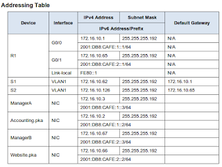
| Addressing Table |
Scenario
Your company has won a contract to set up a small network for a restaurant owner. There are two restaurants near each other, and they all share one connection. The equipment and cabling is installed and the network administrator has designed the implementation plan. You job is to implement the rest of the addressing scheme according to the abbreviated Addressing Table and verify connectivity.
Requirements
· Complete the Addressing Table documentation.
· Configure R1 with IPv4 and IPv6 addressing.
· Configure S1 with IPv4 addressing. S2 is already configured.
· Configure ManagerA with IPv4 and IPv6 addressing. The rest of the clients are already configured.
· Verify connectivity. All clients should be able to ping each other and access the websites on Accounting.pka and Website.pka.
Configure R1 with IPv4 and IPv6 addressing
R1>enable
R1#configure terminal
Enter configuration commands, one per line. End with CNTL/Z.
R1(config)#ipv6 unicast-routing
R1(config)#interface g0/0
R1(config-if)#ip address 172.16.10.1 255.255.255.192
R1(config-if)#ipv6 address FE80::1 link-local
R1(config-if)#no shutdown
R1(config-if)#
%LINK-5-CHANGED: Interface GigabitEthernet0/0, changed state to up
%LINEPROTO-5-UPDOWN: Line protocol on Interface GigabitEthernet0/0, changed state to up
R1(config-if)#exit
R1(config)#
R1(config)#interface g0/1
R1(config-if)#ip address 172.16.10.65 255.255.255.192
R1(config-if)#no shutdown
R1(config-if)#
%LINK-5-CHANGED: Interface GigabitEthernet0/1, changed state to up
%LINEPROTO-5-UPDOWN: Line protocol on Interface GigabitEthernet0/1, changed state to up
R1(config-if)#ipv6 address 2001:DB8:CAFE:2::1/64
R1(config-if)#ipv6 address FE80::1 link-local
R1(config-if)#exit
Configure S1 with IPv4 addressing
S1>enable
S1#configure terminal
Enter configuration commands, one per line. End with CNTL/Z.
S1(config)#interface vlan 1
S1(config-if)#ip address 172.16.10.62 255.255.255.192
S1(config-if)#no shutdown
S1(config-if)#
%LINK-5-CHANGED: Interface Vlan1, changed state to up
%LINEPROTO-5-UPDOWN: Line protocol on Interface Vlan1, changed state to up
S1(config-if)#exit
S1(config)#ip de
S1(config)#ip default-gateway 172.16.10.1
S1(config)#
Configure ManagerA with IPv4 and IPv6 addressing. The rest of the clients are already configured.


8.4.1.2 Packet Tracer - Skills Integration Challenge
Posted by Setiawan on Wednesday, 11 November 2015
2.2.3.3 Packet Tracer - Configuring Initial Switch Settings
Objectives
Part 1: Verify the Default Switch Configuration
Part 2: Configure a Basic Switch Configuration
Part 3: Configure a MOTD Banner
Part 4: Save Configuration Files to NVRAM
Part 5: Configure S2
Background
In this activity, you will perform basic switch configurations. You will secure access to the command-line interface (CLI) and console ports using encrypted and plain text passwords. You will also learn how to configure messages for users logging into the switch. These banners are also used to warn unauthorized users that access is prohibited.
Part 1: Verify the Default Switch Configuration
Step 1: Enter privileged mode.
You can access all switch commands from privileged mode. However, because many of the privileged commands configure operating parameters, privileged access should be password-protected to prevent unauthorized use.
The privileged EXEC command set includes those commands contained in user EXEC mode, as well as the configure command through which access to the remaining command modes are gained.
a. Click S1 and then the CLI tab. Press <Enter>.
b. Enter privileged EXEC mode by entering the enable command:
Switch> enable
Switch#
Notice that the prompt changed in the configuration to reflect privileged EXEC mode.
Step 2: Examine the current switch configuration.
a. Enter the show running-config command.
Switch# show running-config
b. Answer the following questions:
How many FastEthernet interfaces does the switch have?
How many Gigabit Ethernet interfaces does the switch have?
What is the range of values shown for the vty lines?
Which command will display the current contents of non-volatile random-access memory (NVRAM)?
Why does the switch respond with startup-config is not present?
Part 2: Create a Basic Switch Configuration
Step 1: Assign a name to a switch.
To configure parameters on a switch, you may be required to move between various configuration modes. Notice how the prompt changes as you navigate through the switch.
Switch# configure terminal
Switch(config)# hostname S1
S1(config)# exit
S1#
Step 2: Secure access to the console line.
To secure access to the console line, access config-line mode and set the console password to letmein.
S1# configure terminal
Enter configuration commands, one per line. End with CNTL/Z.
S1(config)# line console 0
S1(config-line)# password letmein
S1(config-line)# login
S1(config-line)# exit
S1(config)# exit
%SYS-5-CONFIG_I: Configured from console by console
S1#
Step 3: Verify that console access is secured.
Exit privileged mode to verify that the console port password is in effect.
S1# exit
Switch con0 is now available
Press RETURN to get started.
User Access Verification
Password:
S1>
Step 4: Secure privileged mode access.
Set the enable password to c1$c0. This password protects access to privileged mode.
Note: The 0 in c1$c0 is a zero, not a capital O. This password will not grade as correct until after you encrypt it in Step 8.
S1> enable
S1# configure terminal
S1(config)# enable password c1$c0
S1(config)# exit
%SYS-5-CONFIG_I: Configured from console by console
S1#
Step 5: Verify that privileged mode access is secure.
a. Enter the exit command again to log out of the switch.
b. Press <Enter> and you will now be asked for a password:
User Access Verification
Password:
c. The first password is the console password you configured for line con 0. Enter this password to return to user EXEC mode.
d. Enter the command to access privileged mode.
e. Enter the second password you configured to protect privileged EXEC mode.
f. Verify your configurations by examining the contents of the running-configuration file:
S1# show running-configuration
Notice how the console and enable passwords are both in plain text. This could pose a security risk if someone is looking over your shoulder.
Step 6: Configure an encrypted password to secure access to privileged mode.
The enable password should be replaced with the newer encrypted secret password using the enable secret command. Set the enable secret password to itsasecret.
S1# config t
S1(config)# enable secret itsasecret
S1(config)# exit
S1#
Note: The enable secret password overrides the enable password. If both are configured on the switch, you must enter the enable secret password to enter privileged EXEC mode.
Step 7: Verify that the enable secret password is added to the configuration file.
a. Enter the show running-configuration command again to verify the new enable secret password is configured.
Note: You can abbreviate show running-configuration as
S1# show run
b. What is displayed for the enable secret password?
c. Why is the enable secret password displayed differently from what we configured?
Step 8: Encrypt the enable and console passwords.
As you noticed in Step 7, the enable secret password was encrypted, but the enable and console passwords were still in plain text. We will now encrypt these plain text passwords using the service password-encryption command.
S1# config t
S1(config)# service password-encryption
S1(config)# exit
If you configure any more passwords on the switch, will they be displayed in the configuration file as plain text or in encrypted form? Explain why?
Part 3: Configure a MOTD Banner
Step 1: Configure a message of the day (MOTD) banner.
The Cisco IOS command set includes a feature that allows you to configure messages that anyone logging onto the switch sees. These messages are called message of the day, or MOTD banners. Enclose the banner text in quotations or use a delimiter different from any character appearing in the MOTD string.
S1# config t
S1(config)# banner motd "This is a secure system. Authorized Access Only!"
S1(config)# exit
%SYS-5-CONFIG_I: Configured from console by console
S1#
When will this banner be displayed?
Why should every switch have a MOTD banner?
Part 4: Save Configuration Files to NVRAM
Step 1: Verify that the configuration is accurate using the show run command.
Step 2: Save the configuration file.
You have completed the basic configuration of the switch. Now back up the running configuration file to NVRAM to ensure that the changes made are not lost if the system is rebooted or loses power.
S1# copy running-config startup-config
Destination filename [startup-config]?[Enter]
Building configuration...
[OK]
What is the shortest, abbreviated version of the copy running-config startup-config command?
Step 3: Examine the startup configuration file.
Which command will display the contents of NVRAM?
Are all the changes that were entered recorded in the file?
Part 5: Configure S2
You have completed the configuration on S1. You will now configure S2. If you cannot remember the commands, refer to Parts 1 to 4 for assistance.
Configure S2 with the following parameters:
a. Name device: S2
b. Protect access to the console using the letmein password.
c. Configure an enable password of c1$c0 and an enable secret password of itsasecret.
d. Configure a message to those logging into the switch with the following message:
Authorized access only. Unauthorized access is prohibited and violators will be prosecuted to the full extent of the law.
e. Encrypt all plain text passwords.
f. Ensure that the configuration is correct.
g. Save the configuration file to avoid loss if the switch is powered down.
Soni Setiawan
21:36:00
New Google SEO
Bandung, IndonesiaObjectives
Part 1: Verify the Default Switch Configuration
Part 2: Configure a Basic Switch Configuration
Part 3: Configure a MOTD Banner
Part 4: Save Configuration Files to NVRAM
Part 5: Configure S2
 |
| Topologi yang digunakan |
Background
In this activity, you will perform basic switch configurations. You will secure access to the command-line interface (CLI) and console ports using encrypted and plain text passwords. You will also learn how to configure messages for users logging into the switch. These banners are also used to warn unauthorized users that access is prohibited.
Part 1: Verify the Default Switch Configuration
Step 1: Enter privileged mode.
You can access all switch commands from privileged mode. However, because many of the privileged commands configure operating parameters, privileged access should be password-protected to prevent unauthorized use.
The privileged EXEC command set includes those commands contained in user EXEC mode, as well as the configure command through which access to the remaining command modes are gained.
a. Click S1 and then the CLI tab. Press <Enter>.
b. Enter privileged EXEC mode by entering the enable command:
Switch> enable
Switch#
Notice that the prompt changed in the configuration to reflect privileged EXEC mode.
Step 2: Examine the current switch configuration.
a. Enter the show running-config command.
Switch# show running-config
b. Answer the following questions:
How many FastEthernet interfaces does the switch have?
How many Gigabit Ethernet interfaces does the switch have?
What is the range of values shown for the vty lines?
Which command will display the current contents of non-volatile random-access memory (NVRAM)?
Why does the switch respond with startup-config is not present?
Part 2: Create a Basic Switch Configuration
Step 1: Assign a name to a switch.
To configure parameters on a switch, you may be required to move between various configuration modes. Notice how the prompt changes as you navigate through the switch.
Switch# configure terminal
Switch(config)# hostname S1
S1(config)# exit
S1#
Step 2: Secure access to the console line.
To secure access to the console line, access config-line mode and set the console password to letmein.
S1# configure terminal
Enter configuration commands, one per line. End with CNTL/Z.
S1(config)# line console 0
S1(config-line)# password letmein
S1(config-line)# login
S1(config-line)# exit
S1(config)# exit
%SYS-5-CONFIG_I: Configured from console by console
S1#
Step 3: Verify that console access is secured.
Exit privileged mode to verify that the console port password is in effect.
S1# exit
Switch con0 is now available
Press RETURN to get started.
User Access Verification
Password:
S1>
Step 4: Secure privileged mode access.
Set the enable password to c1$c0. This password protects access to privileged mode.
Note: The 0 in c1$c0 is a zero, not a capital O. This password will not grade as correct until after you encrypt it in Step 8.
S1> enable
S1# configure terminal
S1(config)# enable password c1$c0
S1(config)# exit
%SYS-5-CONFIG_I: Configured from console by console
S1#
Step 5: Verify that privileged mode access is secure.
a. Enter the exit command again to log out of the switch.
b. Press <Enter> and you will now be asked for a password:
User Access Verification
Password:
c. The first password is the console password you configured for line con 0. Enter this password to return to user EXEC mode.
d. Enter the command to access privileged mode.
e. Enter the second password you configured to protect privileged EXEC mode.
f. Verify your configurations by examining the contents of the running-configuration file:
S1# show running-configuration
Notice how the console and enable passwords are both in plain text. This could pose a security risk if someone is looking over your shoulder.
Step 6: Configure an encrypted password to secure access to privileged mode.
The enable password should be replaced with the newer encrypted secret password using the enable secret command. Set the enable secret password to itsasecret.
S1# config t
S1(config)# enable secret itsasecret
S1(config)# exit
S1#
Note: The enable secret password overrides the enable password. If both are configured on the switch, you must enter the enable secret password to enter privileged EXEC mode.
Step 7: Verify that the enable secret password is added to the configuration file.
a. Enter the show running-configuration command again to verify the new enable secret password is configured.
Note: You can abbreviate show running-configuration as
S1# show run
b. What is displayed for the enable secret password?
c. Why is the enable secret password displayed differently from what we configured?
Step 8: Encrypt the enable and console passwords.
As you noticed in Step 7, the enable secret password was encrypted, but the enable and console passwords were still in plain text. We will now encrypt these plain text passwords using the service password-encryption command.
S1# config t
S1(config)# service password-encryption
S1(config)# exit
If you configure any more passwords on the switch, will they be displayed in the configuration file as plain text or in encrypted form? Explain why?
Part 3: Configure a MOTD Banner
Step 1: Configure a message of the day (MOTD) banner.
The Cisco IOS command set includes a feature that allows you to configure messages that anyone logging onto the switch sees. These messages are called message of the day, or MOTD banners. Enclose the banner text in quotations or use a delimiter different from any character appearing in the MOTD string.
S1# config t
S1(config)# banner motd "This is a secure system. Authorized Access Only!"
S1(config)# exit
%SYS-5-CONFIG_I: Configured from console by console
S1#
When will this banner be displayed?
Why should every switch have a MOTD banner?
Part 4: Save Configuration Files to NVRAM
Step 1: Verify that the configuration is accurate using the show run command.
Step 2: Save the configuration file.
You have completed the basic configuration of the switch. Now back up the running configuration file to NVRAM to ensure that the changes made are not lost if the system is rebooted or loses power.
S1# copy running-config startup-config
Destination filename [startup-config]?[Enter]
Building configuration...
[OK]
What is the shortest, abbreviated version of the copy running-config startup-config command?
Step 3: Examine the startup configuration file.
Which command will display the contents of NVRAM?
Are all the changes that were entered recorded in the file?
Part 5: Configure S2
You have completed the configuration on S1. You will now configure S2. If you cannot remember the commands, refer to Parts 1 to 4 for assistance.
Configure S2 with the following parameters:
a. Name device: S2
b. Protect access to the console using the letmein password.
c. Configure an enable password of c1$c0 and an enable secret password of itsasecret.
d. Configure a message to those logging into the switch with the following message:
Authorized access only. Unauthorized access is prohibited and violators will be prosecuted to the full extent of the law.
e. Encrypt all plain text passwords.
f. Ensure that the configuration is correct.
g. Save the configuration file to avoid loss if the switch is powered down.

2.2.3.3 Packet Tracer - Configuring Initial Switch Settings
Posted by Setiawan on Friday, 6 November 2015
2.4.1.2 Packet Tracer -
Skills Integration Challenge
Objectives
Use IOS commands to save the running configuration.
Configure two host devices with IP addresses.
Verify connectivity between the two PC end devices.
Scenario
As a recently hired LAN technician, your network manager has asked you to demonstrate your ability to configure a small LAN. Your tasks include configuring initial settings on two switches using the Cisco IOS and configuring IP address parameters on host devices to provide end-to-end connectivity. You are to use two switches and two hosts/PCs on a cabled and powered network.
Requirements
Use a console connection to access each switch.
Name Class-A and Class-B switches.
Use the xAw6k password for all lines.
Use the 6EBUp secret password.
Encrypt all clear text passwords.
Include the word warning in the message-of-the-day (MOTD) Banner.
Configure addressing for all devices according to the Addressing Table.
Save your configurations.
Verify connectivity between all devices.
Note: Click Check Results to see your progress. Click Reset Activity to generate a new set of requirements. If you click on this before you complete the activity, all configurations will be lost.
Switch Class-A
Class-A#copy running-config startup-config
Switch Class-B
Class-B#copy running-config startup-config
Konfigurasi PC Student-2
Soni Setiawan
17:00:00
New Google SEO
Bandung, IndonesiaObjectives
Configure
hostnames and IP addresses on two Cisco Internetwork Operating System
(IOS) switches using the command-line interface (CLI).
Use
Cisco IOS commands to specify or limit access to the device
configurations.Use IOS commands to save the running configuration.
Configure two host devices with IP addresses.
Verify connectivity between the two PC end devices.
Scenario
As a recently hired LAN technician, your network manager has asked you to demonstrate your ability to configure a small LAN. Your tasks include configuring initial settings on two switches using the Cisco IOS and configuring IP address parameters on host devices to provide end-to-end connectivity. You are to use two switches and two hosts/PCs on a cabled and powered network.
Requirements
Use a console connection to access each switch.
Name Class-A and Class-B switches.
Use the xAw6k password for all lines.
Use the 6EBUp secret password.
Encrypt all clear text passwords.
Include the word warning in the message-of-the-day (MOTD) Banner.
Configure addressing for all devices according to the Addressing Table.
Save your configurations.
Verify connectivity between all devices.
Note: Click Check Results to see your progress. Click Reset Activity to generate a new set of requirements. If you click on this before you complete the activity, all configurations will be lost.
Switch Class-A
Switch>enable
Switch#configure
terminal
Enter
configuration commands, one per line. End with CNTL/Z.
Switch(config)#hostname
Class-A
Class-A(config)#line
console 0
Class-A(config-line)#password
xAw6k
Class-A(config-line)#login
Class-A(config-line)#exit
Class-A(config)#line
vty 0
Class-A(config-line)#password
xAw6k
Class-A(config-line)#login
Class-A(config-line)#exit
Class-A(config)#enable
secret 6EBUp
Class-A(config)#service
password-encryption
Class-A(config)#banner
motd &
Enter
TEXT message. End with the character '&'.
Warning..!!
Authorized Access Only! &
Class-A(config)#interface
vlan 1 Class-A(config-if)#ip add 128.107.20.10 255.255.255.0
Class-A(config-if)#no
shutdown
Class-A(config-if)#endClass-A#copy running-config startup-config
Switch Class-B
Switch>enable
Switch#configure
terminal
Enter
configuration commands, one per line. End with CNTL/Z.
Switch(config)#hostname
Class-B
Class-B(config)#line
console 0
Class-B(config-line)#password
xAw6k
Class-B(config-line)#login
Class-B(config-line)#exit
Class-B(config)#line
vty 0
Class-B(config-line)#password
xAw6k
Class-B(config-line)#login
Class-B(config-line)#exit
Class-B(config)#enable
secret 6EBUp
Class-B(config)#service
password-encryption
Class-B(config)#banner
motd &
Enter
TEXT message. End with the character '&'.
Warning..!!
Authorized Access Only! &
Class-B(config)#interface
vlan 1
Class-B(config-if)#ip add 128.107.20.15 255.255.255.0
Class-B(config-if)#no
shutdown
Class-B(config-if)#endClass-B#copy running-config startup-config
Konfigurasi PC Student-1
 |
| Student-1 |
Konfigurasi PC Student-2
 |
| Student-2 |

2.4.1.2 Packet Tracer - Skills Integration Challenge
Posted by Setiawan on Wednesday, 7 October 2015
2.3.2.5 Packet Tracer - Implement Basic Connectivity
Objectives
Part 1: Perform a Basic Configuration on S1 and S2
Part 1: Perform a Basic Configuration on S1 and S2
Part 2: Configure the PCs
Part 3: Configure the Switch Management Interface
Background
In this activity you will first perform basic switch configurations. Then you will implement basic connectivity by configuring IP addressing on switches and PCs. When the IP addressing configuration is complete, you will use various show commands to verify configurations and use the ping command to verify basic connectivity between devices.
Part 1: Perform a Basic Configuration on S1 and S2
Complete the following steps on S1 and S2.
Step 1: Configure S1 with a hostname.
a. Click S1, and then click the CLI tab.
b. Enter the correct command to configure the hostname as S1.
Step 1: Configure S1 with a hostname.
a. Click S1, and then click the CLI tab.
b. Enter the correct command to configure the hostname as S1.
Switch>enable
Switch#configure terminal
Enter configuration commands, one per line. End with CNTL/Z.
Switch(config)#hostname S1
Step 2: Configure the console and privileged EXEC mode passwords.
a. Use cisco for the console password.
b. Use class for the privileged EXEC mode password.
Switch#configure terminal
Enter configuration commands, one per line. End with CNTL/Z.
Switch(config)#hostname S1
Step 2: Configure the console and privileged EXEC mode passwords.
a. Use cisco for the console password.
b. Use class for the privileged EXEC mode password.
S1(config)#line console 0
S1(config-line)#password cisco
S1(config-line)#login
S1(config-line)#exit
S1(config)#enable secret class
Step 3: Verify the password configurations for S1.
How can you verify that both passwords were configured correctly?
S1(config)#do show running-config
(* Karena masih berada di mode global configuration, tambahkan perintah do untuk mengecek password silakan scroll ke bawah)
!
line con 0
password cisco
login
!
Step 4: Configure a message of the day (MOTD) banner.
Use an appropriate banner text to warn unauthorized access. The following text is an example:
Authorized access only. Violators will be prosecuted to the full extent of the law.
S1(config)#banner motd &
Enter TEXT message. End with the character '&'.
Authorized access only. Violators will be prosecuted to the full extent of the law.&
S1(config)#
Enter TEXT message. End with the character '&'.
Authorized access only. Violators will be prosecuted to the full extent of the law.&
S1(config)#
Step 5: Save the configuration file to NVRAM.
Which command do you issue to accomplish this step?
S1(config)#do copy running-config startup-config
Step 6: Repeat Steps 1 to 5 for S2.
Step 6: Repeat Steps 1 to 5 for S2.
Switch(config)#hostname S2
S2(config)#line console 0
S2(config-line)#password cisco
S2(config-line)#login
S2(config-line)#exit
S2(config)#enable secret class
S2(config-line)#password cisco
S2(config-line)#login
S2(config-line)#exit
S2(config)#enable secret class
S2(config)#do show running-config
S2(config)#banner motd &
Enter TEXT message. End with the character '&'.
Authorized access only. Violators will be prosecuted to the full extent of the law.&
S2(config)#
Enter TEXT message. End with the character '&'.
Authorized access only. Violators will be prosecuted to the full extent of the law.&
S2(config)#
S2(config)#do copy running-config startup-config
Part 2: Configure the PCs
Configure PC1 and PC2 with IP addresses.
Step 1: Configure both PCs with IP addresses.
a. Click PC1, and then click the Desktop tab.
b. Click IP Configuration. In the Addressing Table above, you can see that the IP address for PC1 is 192.168.1.1 and the subnet mask is 255.255.255.0. Enter this information for PC1 in the IP Configuration window.
 |
| Konfigurasi PC 1 |
c. Repeat steps 1a and 1b for PC2.
 |
| Konfigurasi PC 2 |
Step 2: Test connectivity to switches.
a. Click PC1. Close the IP Configuration window if it is still open. In the Desktop tab, click Command Prompt. .
b. Type the ping command and the IP address for S1, and press Enter.
Part 3: Configure the Switch Management Interface
Configure S1 and S2 with an IP address.
Step 1: Configure S1 with an IP address.
Switches can be used as a plug-and-play device, meaning they do not need to be configured for them to work. Switches forward information from one port to another based on Media Access Control (MAC) addresses. If this is the case, why would we configure it with an IP address?
Use the following commands to configure S1 with an IP address.
S1 #configure terminal
Enter configuration commands, one per line. End with CNTL/Z.
S1(config)# interface vlan 1
S1(config-if)# ip address 192.168.1.253 255.255.255.0
S1(config-if)# no shutdown
%LINEPROTO-5-UPDOWN: Line protocol on Interface Vlan1, changed state to up
S1(config-if)#
S1(config-if)# exit
S1#
Why do you need to enter the no shutdown command?
Step 2: Configure S2 with an IP addresses.
Use the information in the addressing table to configure S2 with an IP address.
S2 #configure terminal
Enter configuration commands, one per line. End with CNTL/Z.
S2(config)# interface vlan 1
S2(config-if)# ip address 192.168.1.254 255.255.255.0
S2(config-if)# no shutdown
%LINEPROTO-5-UPDOWN: Line protocol on Interface Vlan1, changed state to up
S2(config-if)#
S2(config-if)# exit
S2#
Step 3: Verify the IP address configuration on S1 and S2.
Use the show ip interface brief command to display the IP address and status of the all the switch ports and interfaces. Alternatively, you can also use the show running-config command.
Step 4: Save configurations for S1 and S2 to NVRAM.
Which command is used to save the configuration file in RAM to NVRAM?
S1#copy running-config startup-config
S2#copy running-config startup-config
Step 5: Verify network connectivity.
Network connectivity can be verified using the ping command. It is very important that connectivity exists throughout the network. Corrective action must be taken if there is a failure. Ping S1’s and S2's IP address from PC1 and PC2.
a. Click PC1, and then click the Desktop tab.
b. Click Command Prompt.
c. Ping the IP address for PC2.
d. Ping the IP address for S1.
e. Ping the IP address for S2.
Note: You can also use the same ping command on the switch CLI and on PC2.
All pings should be successful. If your first ping result is 80%, retry; it should now be 100%. You will learn why a ping may fail the first time later in your studies. If you are unable to ping any of the devices, recheck your configuration for errors.
UPDATE !!!
Saya telah mengunggah video tutorial di Youtube.

2.3.2.5 Packet Tracer - Implementing Basic Connectivity
Posted by Setiawan on Friday, 2 October 2015
2.3.1.5 Packet Tracer - Configuring PVST+
 Objectives
Part 1: Configure VLANs
Part 2: Configure Spanning Tree PVST+ and Load Balancing
Part 3: Configure PortFast and BPDU Guard
Step 1: Enable the user ports on S1, S2, and S3 in access mode.
Refer to the topology diagram to determine which switch ports (S1, S2, and S3) are activated for end-user device access. These three ports will be configured for access mode and enabled with the no shutdown command.
S1>ena
S1#configure
terminal
Enter
configuration commands, one per line. End with CNTL/Z.
S1(config)#interface
fastEthernet 0/6
S1(config-if)#switchport
mode access
S1(config-if)#switchport
access vlan 30
%
Access VLAN does not exist. Creating vlan 30
S1(config-if)#no shutdown
S2>ena
S2#configure
terminal
Enter
configuration commands, one per line. End with CNTL/Z.
S2(config)#interface fastEthernet 0/18
S2(config-if)#switchport mode access
S2(config-if)#switchport access vlan 20
% Access VLAN does not exist. Creating
vlan 20
S2(config-if)#no shutdown
S3>ena
S3#configure terminal
Enter configuration commands, one per line. End with CNTL/Z.
S3(config)#interface fastEthernet 0/11
S3(config-if)#switchport mode access
S3(config-if)#switchport access vlan 10
% Access VLAN does not exist. Creating vlan 10
S3(config-if)#no shutdown
Step 2: Create VLANs.
Using the appropriate command, create VLANs 10, 20, 30, 40, 50, 60, 70, 80, and 99 on all of the switches.
S1(config)#vlan 10
S1(config-vlan)#vlan 20
S1(config-vlan)#vlan 30
S1(config-vlan)#vlan 40
S1(config-vlan)#vlan 50
S1(config-vlan)#vlan 60
S1(config-vlan)#vlan 70
S1(config-vlan)#vlan 80
S1(config-vlan)#vlan 99
S1(config-vlan)#
(lakukan hal yang sama di switch S2 dan S3)
Step 3: Assign VLANs to switch ports.
Port assignments are listed in the table at the beginning of the activity. Save your configurations after assigning switch ports to the VLANs.
Port assignments are listed in the table at the beginning of the activity. Save your configurations after assigning switch ports to the VLANs.
Step 4: Verify the VLANs.
Use the show vlan brief command on all switches to verify that all VLANs are registered in the VLAN table.
Use the show vlan brief command on all switches to verify that all VLANs are registered in the VLAN table.
S1#show vlan brief
Step 5: Assign the trunks to native VLAN 99.
Use the appropriate command to configure ports F0/1 to F0/4 on each switch as trunk ports, and assign these trunk ports to native VLAN 99.
Configure the management interface on all three switches with an address.Verify that the switches are correctly configured by pinging between them.
Use the appropriate command to configure ports F0/1 to F0/4 on each switch as trunk ports, and assign these trunk ports to native VLAN 99.
Configure the management interface on all three switches with an address.Verify that the switches are correctly configured by pinging between them.
S1#configure terminal
Enter configuration commands, one per line. End with CNTL/Z.
S1(config)#interface range fa0/1-4
S1(config-if-range)#switchport mode trunk
S1(config-if-range)#switchport trunk native vlan 99
S1(config-if-range)#exit
S1(config)#interface vlan 99
S1(config-if)#ip address 172.31.99.1 255.255.255.0
S1(config-if)#end
S2#configure terminal
Enter configuration commands, one per line. End with CNTL/Z.
S2(config)#interface range fa0/1-4
S2(config-if-range)#switchport mode trunk
S2(config-if-range)#exit
S2(config)#interface vlan 99
S2(config-if)#ip address 172.31.99.2 255.255.255.0
S2(config-if)#end
S3#configure terminal
Enter configuration commands, one per line. End with CNTL/Z.
S3(config)#interface range fa0/1-4
S3(config-if-range)#switchport mode trunk
S3(config-if-range)#exit
S3(config)#interface vlan 99
S3(config-if)#ip address 172.31.99.3 255.255.255.0
S3(config-if)#end
Part 2: Configure Spanning Tree PVST+ and Load Balancing
Step 1: Configure STP mode.
Use the spanning-tree mode command to configure the switches so they use PVST as the STP
Use the spanning-tree mode command to configure the switches so they use PVST as the STP
mode.
S1#configure terminal
Enter configuration commands, one per line. End with CNTL/Z.
S1(config)#spanning-tree mode pvst
S1(config)#
S2#configure terminal
Enter configuration commands, one per line. End with CNTL/Z.
S2(config)#spanning-tree mode pvst
S2(config)#
S3#configure terminal
Enter configuration commands, one per line. End with CNTL/Z.
S3(config)#spanning-tree mode pvst
S3(config)#
Step 2: Configure Spanning Tree PVST+ load balancing.
a. Configure S1 to be the primary root for VLANs 1, 10, 30, 50, and 70. Configure S3 to be the primary root for VLANs 20, 40, 60, 80, and 99. Configure S2 to be the secondary root for all VLANs.
S1(config)#spanning-tree vlan 10,30,50,70 root primary
S2(config)#spanning-tree vlan 1,10,20,30,40,50,60,70,80,99 root secondary
S3(config)#spanning-tree vlan 20,40,60,80 root primary
b. Verify your configurations using the show spanning-tree command.
S1(config)#do show spanning-tree
S2(config)#do show spanning-tree
S3(config)#do show spanning-tree
Part 3: Configure PortFast and BPDU Guard
Step 1: Configure PortFast on the switches.
PortFast causes a port to enter the forwarding state almost immediately by dramatically decreasing the time of the listening and learning states. PortFast minimizes the time it takes for the server or workstation to come online. Configure PortFast on the switch interfaces that are connected to PCs.
PortFast causes a port to enter the forwarding state almost immediately by dramatically decreasing the time of the listening and learning states. PortFast minimizes the time it takes for the server or workstation to come online. Configure PortFast on the switch interfaces that are connected to PCs.
S1(config)#int fa0/6
S1(config-if)#spanning-tree portfast
S1(config-if)#exit
S2(config)#int fa0/18
S2(config-if)#spanning-tree portfast
S2(config-if)#exit
S3(config)#int fa0/11
S3(config-if)#spanning-tree portfast
S3(config-if)#exit
Step 2: Configure BPDU guard on the switches.The STP PortFast BPDU guard enhancement allows network designers to enforce the STP domain borders and keep the active topology predictable. The devices behind the ports that have STP PortFast enabled are unable to influence the STP topology. At the reception of BPDUs, the BPDU guard operation disables the port that has PortFast configured. The BPDU guard transitions the port into the err-disable state, and a message appears on the console. Configure BPDU guard on switch interfaces that are connected to PCs.
S1(config)#int fa0/6
S1(config-if)#spanning-tree bpduguard enable
S1(config-if)#
S2(config)#int fa0/18
S2(config-if)#spanning-tree bpduguard enable
S2(config-if)#
S3(config)#int fa0/11
S3(config-if)#spanning-tree bpduguard enable
S3(config-if)#
Step 3: Verify your configuration.
Use the show running-configuration command to verify your configuration.
Use the show running-configuration command to verify your configuration.

